Inputs
The client gives you a set of requirements. It the example bellow, it was given as a document under the name ‘Specification of Services’ (Sepia example, in Brazil), but every client works and communicates differently. It contains a lot of information on how the project should be done. In an ideal scenario, the commercial specialist is able to work fine with just that document. Nonetheless, there is commonly also a phase of information exchange between the client and the company, where the commercial specialist can ask for further information.
The input values, format and amount of information vary between different clients and projects. But here we have a list of usually given parameters from a client:
CRS
Coordinate Reference System. Provides a map projection that matches the client’s coordinates based on the curvature of the Earth.

Source polygon and receiver polygon
These can be provided on several different types: as a shapefile, a csv, an image with points… Is the commercial specialist who takes the data given and obtains a polygon with it.
Further note: “The source polygons are often not provided at all, and instead we’re told an inline/crossline/radial offset requirement with which to generate our own source polygons. This may require some clarification, but in the case of radial offset requirements, these are often generated using the “Buffer” processing tool in QGIS. The distance of this buffer depends on requirements, but it is common to find that this figure is 50% of the radial offset requirement. In reality, if the defined receiver area is the same as the full fold area, we would need to extend the source halo to the full radial offset distance from the receiver polygon. For non-radial offset requirements, we would need to extend the source halo inline and crossline by their respective offset values, which may or may not match each other”.
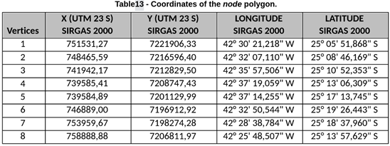
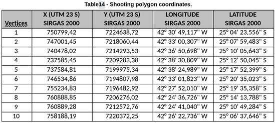
The Sepia example has an input of two tables (bellow) with a few coordinates in X-Y format and in longitude-latitude format; although the team uses only X-Y in their workflow. These coordinates are transformed to txt files like these: receiver polygon, source polygon

Additional polygons
You may get additional polygons, for example in the case of a densification area. These can also be provided in several different ways.
Receiver Point and Line Interval
Numeric values for Receiver Point Interval and Receiver Line Interval.

IL: in line distance between nodes, is the RPI.
XL: cross line distance between nodes, is the RLI.
Source Point and Line
Numeric values for Source Point Interval and Source Line Interval.
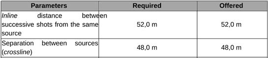
IL: in line distance between shots, is the SPI.
XL: cross line distance between sources, is the SLI.
Stagger
Stagger / Node mesh geometry. Stagger = YES for hexagonal mesh.

Method of the project
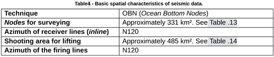
Like OBN (Ocean Bottom Node) which Sardine is meant to handle. They can also receive MTS proposal (Marine Toward Steamer).
Value of the Azimuth
Is generally provided as degrees clockwise from the north.
Number of sources in each vessel
This information you can commonly find in the source table. Dual or ‘flip flop’ means two sources. Triple or ‘flip flap flop’ means three sources.

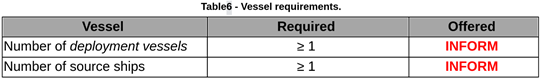
Number of source and receiver vessels
Shots
Minimum time between shots: how many seconds must pass between shots. This is not an input for Sardine, but it is used to verify the source speed, by checking that we don’t need to slow down the vessel’s speed to respect this requirement.

Minimum recording time for each shot. This is not an input for the excel.
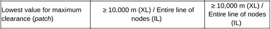
Crossline offset
Water depth
Usually given as a range so we choose the mean value (2200 m):

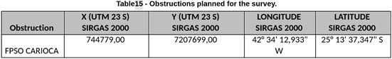
Obstructions
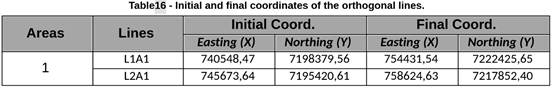
Orthogonal lines
Others
And of course, a lot more requirements that do not concern the current workflow for Sardine or are just not included here.
Requirements
ID |
Title |
Status |
|---|---|---|
Clients may not provide source polygons; they may provide offset opens instead. |
open |
|
Obstructions, PIES, and slopes affect receiver operations and require manual time adjustments. |
open |
|
Densification areas require manual handling and may benefit from future automation. |
open |